
Guide
What is 5-axis CNC machining, and does your part really need it?
5-axis CNC machining is milling on a machine with three linear axes (X, Y and Z) plus two rotary axes, so the tool can reach the part from many directions in one setup. It comes in two forms: 3+2 (indexed) machining, where the rotary axes only tilt the part or tool and then lock while the three linear axes cut, and simultaneous five-axis, where all five axes move together. Most prismatic parts with features on several faces need at most 3+2 or extra setups; only free-form surfaces and true compound undercuts need simultaneous motion.
By Saola Manufacturing engineering team · Published · Updated
This guide is for engineers and buyers deciding whether a drawing must go to a five-axis shop, or whether a three-axis plant with good fixturing can make it. The machine definitions come from the scope of ISO 10791-6 (2014), the international test standard for the kinematic accuracy of machining centers with one or two rotary axes; the 3+2 definition is taken from a National Taiwan University study (2014). Turned parts that also need milled features are a different routing question, covered in our mill-turn guide.
On this page
What does the fifth axis actually add?
Two rotary axes let the machine point the tool at the part from almost any direction, so features on several faces or on angled planes can be cut in one clamping instead of several.
A three-axis machining center moves the tool in X, Y and Z only; the tool always points the same way. ISO 10791-6 describes five-axis machining centers as having three orthogonal linear axes and two rotary axes, named A, B or C depending on which linear axis they turn about. Adding those two axes removes re-clamping, which is where most face-to-face position error on a multi-sided part comes from.
It also lets the tool tilt to the surface. A study of tilted tool axis machining uses that tilt, indexed with the two rotary axes, to give a ball end mill a stable cutting attitude while the three linear axes feed. That is a quality gain, not only an access gain.
| Point | 3-axis with extra setups | 3+2 (indexed) five-axis | Simultaneous five-axis |
|---|---|---|---|
| Rotary axes during cutting | None; part is re-clamped | Tilted, then locked | Moving with the linear axes |
| Tool path | 3-axis program per setup | 3-axis program on a tilted work plane | Full five-axis path from CAM |
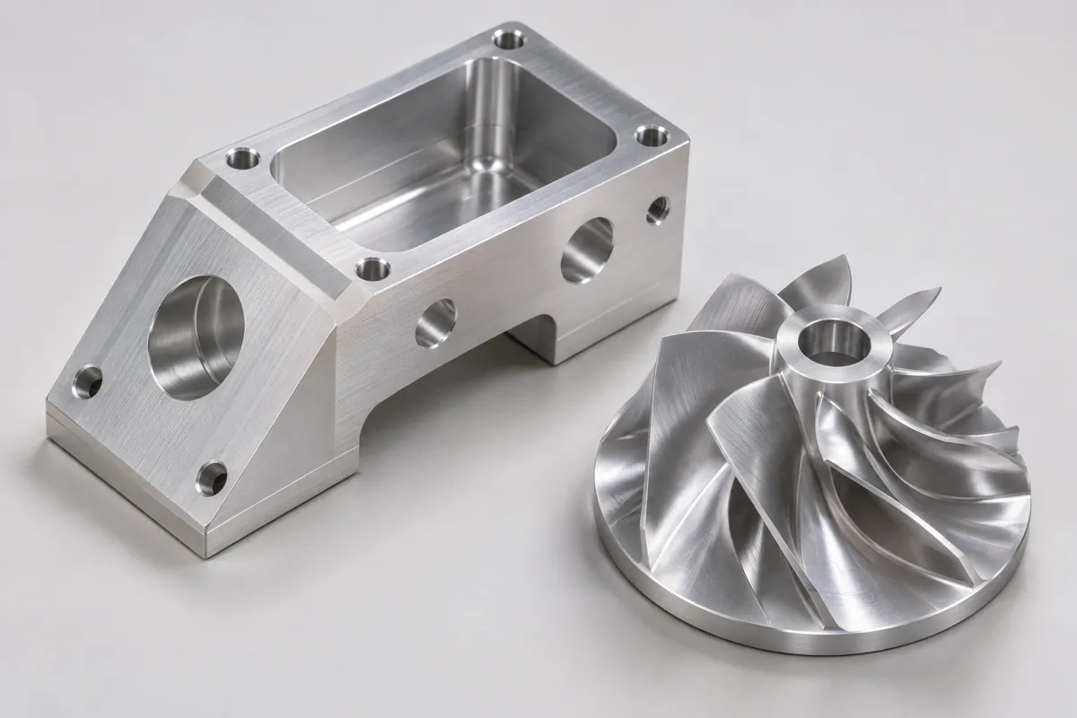
| Features it suits | Prismatic parts, few faces | Holes, pockets and faces on several angled planes | Free-form surfaces, blades, ports, compound undercuts |
| Main accuracy risk | Re-clamping between faces | Rotary positioning and work-plane setup | Combined geometric and servo errors of all axes |
| Programming effort | Lowest | Moderate | Highest; simulation strongly advised |
What is the difference between 3+2 and simultaneous five-axis?
In 3+2 machining the two rotary axes tilt the part or tool to a fixed angle and lock, and a normal 3-axis program runs on that tilted plane; in simultaneous five-axis all five axes move together during the cut.
The National Taiwan University study puts it plainly: in 3+2 axis machining, a 3-axis program is executed with the tool locked in a tilted position by the two rotary axes, and typical features on tilted planes such as holes and grooves are cut this way. Simultaneous motion is needed only when the tool orientation must change continuously along the path, as on an impeller blade, a turbine-style port or a sculpted mold surface.
For a buyer, the difference shows up in who can make the part. Much of the five-axis work on prismatic parts is done as 3+2, and that is the right method for most of them. Asking “does this need simultaneous motion?” narrows the supplier list honestly.
Which five-axis machine layouts exist?
ISO 10791-6 groups five-axis machining centers into three layouts: both rotary axes in the spindle head, both on the workpiece side, or a swivel head combined with a rotary table.
The layout decides how big and heavy a part can be and how much of it the tool can reach. A trunnion table (both axes on the workpiece side) tilts the part itself, which suits small and medium parts. A head-head machine keeps the part still and moves the spindle, which suits large parts. The standard gives separate kinematic tests for each layout in its annexes, because their errors behave differently.
| Layout | Where the rotary axes are | Typical fit |
|---|---|---|
| Head-head (Annex A) | Both in the spindle head | Large or heavy parts that should not move |
| Table-table, trunnion (Annex B) | Both on the workpiece side | Small and medium parts; good access to five faces |
| Head-table (Annex C) | Swivel head plus rotary table | Long parts and mixed work |
Is five-axis machining more accurate than three-axis?
Not automatically: it removes re-clamping error between faces, but it adds rotary-axis errors, and the combined effect of geometric and servo errors across five axes is harder to measure and separate.
That is not a sales argument; it is why the test standards exist. NIST noted in 2012 that standards committees were developing test methods for the simultaneous motion of all five axes, and that the compound effect of individual geometric and servo errors makes the results hard to analyze. ISO 10791-6 specifies the kinematic tests used to check the paths produced by simultaneous movement of linear and rotary axes.
For the drawing, the useful conclusion is to tolerance what matters to function and datum it sensibly. A tight position tolerance between two faces is easier to hold in one clamping, whichever machine does it, and a shop can often meet it on three axes with a well-designed fixture.
How can you tell if your part needs simultaneous five-axis?
It needs simultaneous five-axis only if some surface cannot be cut with the tool at any fixed orientation: free-form surfaces, blended walls that twist along their length, or undercuts reachable only by a moving tool axis.
Run through the part face by face. If every feature can be reached with the tool perpendicular to some flat plane, the part is a 3+2 or multi-setup part. Holes on a bolt circle tilted at a compound angle, pockets on several sides and chamfers on angled faces all fall into that group. A ruled or sculpted surface that changes angle continuously does not.
Then look at the cost of setups. A family of small parts with features on two or three faces is often cheaper on three axes with dedicated fixtures at volume, while a one-off with six angled faces is cheaper in one five-axis clamping. Our design for machining guide covers how to count the setups a part really needs.
How should the drawing and RFQ handle multi-face parts?
Define the angled features from datums with basic angles and position tolerances, and leave the machine choice to the supplier unless a surface truly requires simultaneous motion.
A drawing that dimensions a tilted hole by a basic angle and a position tolerance to datum faces tells any competent shop what to hold, whatever the machine. Send a STEP model with the PDF, because angled and free-form features are easier to quote and program from the model, and mark the faces where tool marks or blend lines matter cosmetically.
If you believe the part needs simultaneous motion, say which surface and why. That lets a supplier answer honestly instead of quoting a method it cannot run.
Can Saola machine five-axis parts?
Simultaneous five-axis machining is not offered at our lead plant, so parts whose surfaces need it are not a fit; multi-face prismatic parts are reviewed for setups and fixturing at drawing review.
The CNC milling work at the lead plant runs on machining centers and is mostly second-operation machining of castings: bores, faces and threads on die-cast and sand-cast housings. The review states plainly whether the setups a part needs fit that equipment. New parts get a first-article inspection report and every lot a dimensional inspection record.
For a casting with features on several faces, the most useful RFQ note is which faces are datums and which features are related to them, so the fixturing plan can be agreed before the quote.
Frequently asked
Is 3+2 machining real five-axis machining?
It uses a five-axis machine, but only positions with the rotary axes. For most parts with features on several faces it is the right method, and it is simpler to program and check than simultaneous motion.
What are the A, B and C axes?
They are rotary axes about X, Y and Z respectively. ISO 10791-6 covers machining centers with three linear axes plus one or two rotary axes named A, B or C.
Does five-axis machining reduce cost?
It can, by cutting setups and fixtures, especially on low volumes of complex parts. At higher volume, dedicated fixtures on three-axis machines are often competitive for parts that do not need tool tilt.
Is a four-axis machine enough?
Often, when all the features sit around one axis, such as holes around a cylinder or faces on a hexagonal body. A rotary fourth axis indexes the part about that one axis only.
Do I need to tell the supplier which machine to use?
No. Specify the geometry and tolerances, and only flag surfaces you believe need simultaneous motion. Naming a machine restricts the quote without improving the part.
Sources
- ISO 10791-6:2014, Test conditions for machining centers, Part 6: Accuracy of speeds and interpolations (scope), ISO via EVS catalog, 2014
- ISO 10791-6:2014-12, table of contents (Annexes A to C by rotary-axis configuration), DIN, 2015
- Virtual Machine Tool Evaluation of Standardized 5-Axis Performance Tests, Fesperman, Moylan and Donmez, National Institute of Standards and Technology, 2012
- Tool Path Transformation of Tilted Plane Machining Features for Five-axis Numerical Control Programming, National Taiwan University, December 2014
- Yamada, Kondo, Tanaka and Kishinami, Tilted Tool Axis Machining on 5-Axis Machine Tools, International Journal of Automation Technology Vol. 1, Fuji Technology Press, 2007