
Guide
Dial indicator vs dial test indicator: which one should check your part?
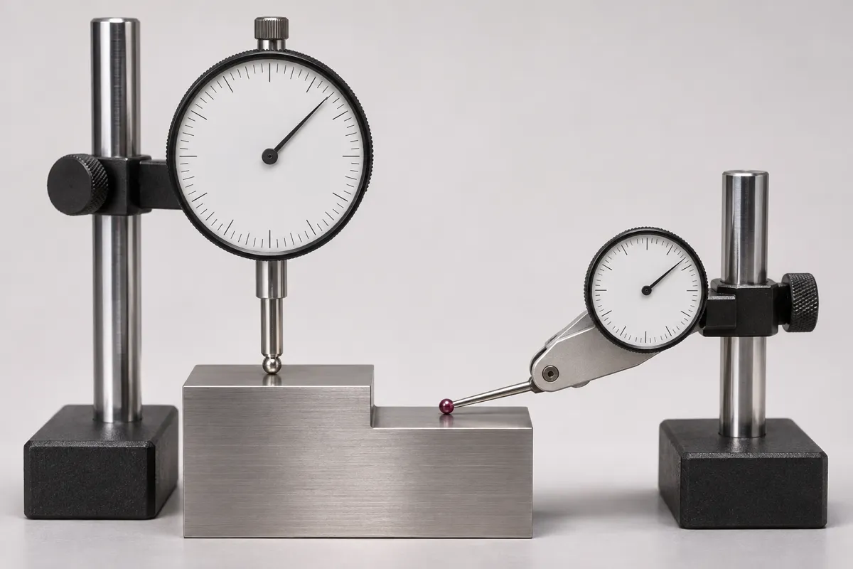
A dial indicator is a plunger-type gauge whose spindle moves in a straight line along its own axis, while a dial test indicator is a lever-type gauge whose stylus swings through a small arc. Use the dial indicator for travel and height comparison along one axis, and the test indicator for runout, alignment and comparison against a master in tight spaces, with the stylus set as close to parallel with the surface as possible.
By Saola Manufacturing engineering team · Published · Updated
This guide is for buyers and quality engineers who read inspection reports, and for engineers deciding how a runout or flatness note will actually be checked. Instrument behavior comes from Mitutoyo’s dial test indicator manual (2022) and the Mitutoyo Quick Guide to dial indicators and dial test indicators (2009), which reproduces extracts of JIS B7503 and JIS B7533; the US standard for plunger dial indicators is ASME B89.1.10M. How much any of these readings can be trusted for a given tolerance is the subject of our measurement uncertainty budget guide.
On this page
What is the difference between a dial indicator and a dial test indicator?
A dial indicator measures along its plunger axis over a long travel, while a dial test indicator measures the swing of a lever stylus over a short range and reads correctly only when that stylus is set near parallel to the surface.
The plunger type is the one on a magnetic base over a surface plate, often with a long range and a revolution counter. The lever type is the small, flat-bodied gauge with a pointed stylus that reaches into a bore or across a shoulder. The Mitutoyo Quick Guide lists different standards for them: JIS B7503 for dial indicators and JIS B7533 for dial test indicators, with separate accuracy tables. In the US, ASME B89.1.10M covers dial indicators for linear measurement and is the standard most plunger indicators are sold against.
Machinists use both, and the confusion is mostly in the names. “Test indicator”, “lever indicator” and “DTI” usually mean the lever type; “dial indicator” or “dial gauge” usually means the plunger type. An inspection report should name which one it was.
| Point | Dial indicator (plunger) | Dial test indicator (lever) |
|---|---|---|
| Measuring motion | Straight line along the spindle axis | Arc of the stylus about its pivot |
| Measuring ranges in the JIS extracts | Up to 10 mm and beyond, depending on graduation | 0.2 to 1.0 mm, depending on graduation |
| Alignment rule | Spindle in line with the measuring direction | Stylus near parallel to the surface, measuring direction at right angles to the stylus |
| Best uses | Height and depth comparison, travel, setting on a stand | Runout, bore and face alignment, tramming, comparison to a gauge block |
| Main error source | Spindle tilt, stand flex, measuring force varying with position | Stylus angle (cosine effect), wrong contact point length |
| Role on an inspection report | Comparator against a set height or master | Variation reading (runout, TIR) or comparison against a master |
What is cosine error, and how big does it get?
Cosine error is the reading error caused when the instrument’s measuring direction is not aligned with the direction you want to measure; on a test indicator it grows quickly with stylus angle, and per the Mitutoyo tables a reading at 60° must be halved.
Per the Mitutoyo Quick Guide, the measuring direction of a dial test indicator is at right angles to a line through the contact point and the stylus pivot, so the stylus should be set to keep that angle small. When it cannot be, multiply the reading by the compensation value for the actual angle. The two Mitutoyo documents round the 30° and 40° values differently, so only the angles where they agree are tabulated; for the others, use the cosine of the angle or the table in your own instrument’s manual.
The plunger indicator has the same physics in a milder form. Per the Mitutoyo Quick Guide, it should be mounted with its spindle in line with the intended measurement direction to avoid cosine-effect error; a few degrees of tilt on a stand is a small error, but it is a systematic one, and it adds directly to the uncertainty of the reading.
| Stylus angle to the surface | Compensation value (multiply the reading) | Reading of 0.100 mm becomes |
|---|---|---|
| 10° | 0.98 | 0.098 mm |
| 20° | 0.94 | 0.094 mm |
| 50° | 0.64 | 0.064 mm |
| 60° | 0.50 | 0.050 mm |
Which indicator should be used for runout and concentricity checks?
Use a dial test indicator for runout on turned diameters and faces, because its short stylus reaches the surface at a low angle and its fine graduations suit the small variation being read.
For runout, the absolute reading does not matter; the full swing of the needle in one revolution does. A steep stylus angle scales that swing up, because the dial reads more than the true displacement, so an uncompensated reading makes the part look worse than it is and can reject a good part. A good practice is to set the stylus near parallel to the surface and note the setup on the report.
A plunger indicator works for runout on large, open diameters and for face runout where it can sit square to the face. For a turned part held between centers or in V-blocks, either can be correct, so the drawing note and the datum scheme matter more than the brand of gauge.
Can a dial test indicator measure a size or a height directly?
Not on its own: a dial test indicator is a comparator, so it measures a size only by comparing the part against a gauge block or master set to the nominal dimension.
Its range is too short to read a dimension from scratch. Per the JIS B7533 extract in the Mitutoyo Quick Guide, lever indicators with 0.01 mm graduation have measuring ranges of 0.5 to 1.0 mm, and those with 0.002 mm graduation about 0.2 to 0.28 mm. Used with a gauge block stack and a height stand, it gives an excellent difference reading; used across a long step, it runs out of range or picks up large angle errors.
Mitutoyo’s dial test indicator manual adds two cautions that matter for reports: use only a contact point of the length printed on the dial face, because a different length causes significant error, and confirm accuracy after replacing a contact point. A setup that mixes stylus lengths between the master and the part will not agree with a gauge lab.
Which instrument should an inspection report list?
List the instrument actually used for each characteristic, with its type, graduation and identification, and for comparator readings also the master or gauge block it was set to.
A typical line such as “Runout A: 0.012 mm TIR, dial test indicator 0.002 mm graduation, part in V-blocks on datum A” tells the reader both the result and whether the method matches the drawing. A bare number with “indicator” in the method column does not. When results from two sites differ, the first question is usually which indicator type and setup each one used.
For tolerances that are a large fraction of the indicator’s graduation or range, the method itself should be agreed before the order. The uncertainty budget guide shows how to check that the instrument is fit for the tolerance.
How are indicator checks handled on a Saola order?
The method for each characteristic is agreed at drawing review and recorded on the first-article inspection report for new parts and on the dimensional inspection record for every lot.
The lead plant’s inspection equipment includes a 2D optical vision measuring instrument, a height gauge and a hardness tester, and there is no CMM, so features that would usually go to a CMM are discussed at review and a practical method is agreed in writing. For turned parts from our CNC turning line, where runout and concentricity callouts are common, say in the RFQ how you check them at receiving, so both sides use the same setup.
If your quality plan requires a specific instrument type for a characteristic, write it on the drawing or the PO rather than leaving it to custom.
Frequently asked
Is a test indicator more accurate than a dial indicator?
Not inherently. Per the JIS extracts in the Mitutoyo Quick Guide, both come in fine graduations; the test indicator simply has a short range and is easier to use in tight spaces, while the plunger type covers longer travel.
Why does my test indicator read high on a steep angle?
Because of the cosine effect. The stylus moves along an arc, so at a steep angle the dial shows more movement than the true displacement; multiply by the compensation value for that angle, or reset the stylus flatter.
What is an involute contact point?
Per the Mitutoyo Quick Guide, it is a custom-made contact point shaped to compensate automatically for stylus angles from 0 to 30 degrees, so no manual correction is needed in that range.
Does mounting position change the reading?
It can. The Mitutoyo Quick Guide notes that with the spindle horizontal or contact point up, measuring force is lower than with the contact point down, so operation and repeatability should be checked in that position.
Can an indicator replace a CMM for position tolerances?
For simple cases with a fixture and masters, sometimes; for multi-feature position tolerances, usually not. Agree the method in writing before the order rather than after a dispute.
Sources
- Dial Test Indicator user’s manual, 513 series (513-474-10E), Mitutoyo Corporation, published 1 February 2022
- Quick Guide to Precision Measuring Instruments: Dial Indicators/Dial Test Indicators (with JIS B7503 and B7533 extracts), Mitutoyo Corporation, 2009
- ASME B89.1.10M-2001 (reaffirmed), Dial Indicators (for Linear Measurements), ASME, 2001, reaffirmed 2021