
Guide
What does an angular tolerance control, and how is it different from angularity?
An angular tolerance is the permitted deviation, in degrees and minutes, on an angle dimension such as "30°" between two features of a part. Short answer: it allows the angle to vary within a wedge-shaped zone that grows wider the farther you go from the vertex, and it controls only the general direction of the line, not its form; GD&T angularity, by contrast, holds the surface inside two parallel planes of constant width at a basic angle to a datum.
By Saola Manufacturing engineering team · Published · Updated
Angle tolerances are some of the least thought-about numbers on a drawing. Many title blocks carry a default such as half a degree either way, copied from one drawing to the next, and nobody checks what that means at the end of a long face. This guide explains what a plus-or-minus angle actually allows, where the common default values come from, when to switch to angularity, and how angles are measured. The geometric tolerance comparison itself is covered in the perpendicularity vs angularity guide.
On this page
What does a plus-or-minus angle tolerance actually allow?
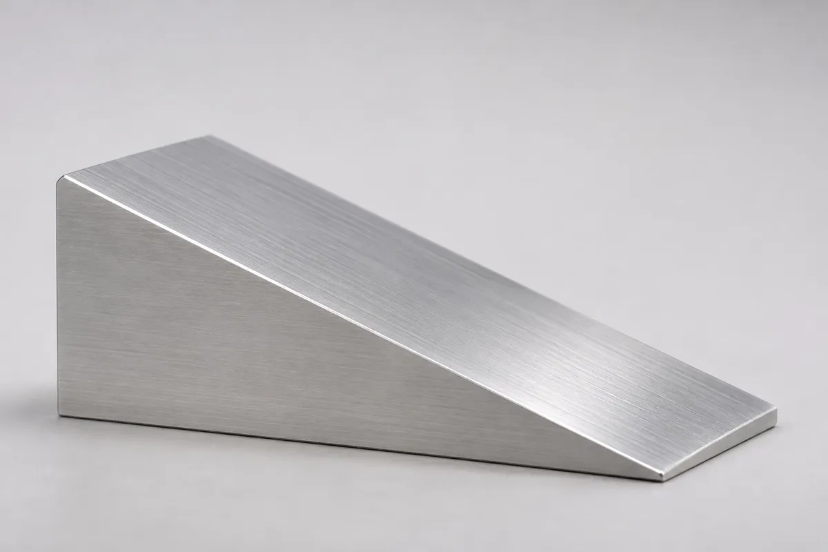
It allows each line element of the feature to sit at any angle between the two limits, measured from the vertex, so the zone is a wedge rather than a band. The farther a point is from the vertex, the more it can move sideways.
That wedge shape is the most important thing to understand. Half a degree means very little at the vertex and a lot at the end of a long leg. The sideways offset at the end of the leg equals the leg length times the tangent of the angle deviation, so the same angle tolerance allows ten times the offset on a leg ten times as long. If the far end of a chamfer, a taper or an angled face mates with something, check the offset there, not just the angle.
The second point is what the tolerance does not control. The general tolerancing standard ISO 2768-1 states that tolerances given in angular units control only the general orientation of lines or line elements of surfaces, not their form deviations. A wavy or crowned angled face can pass an angle check while its form is poor. If the form matters, add a flatness or profile control.
| Angle deviation, either way | 10 mm leg | 50 mm leg | 120 mm leg | 400 mm leg |
|---|---|---|---|---|
| 1° | 0.17 mm | 0.87 mm | 2.09 mm | 6.98 mm |
| 0°30' (0.5°) | 0.09 mm | 0.44 mm | 1.05 mm | 3.49 mm |
| 0°20' | 0.06 mm | 0.29 mm | 0.70 mm | 2.33 mm |
| 0°10' | 0.03 mm | 0.15 mm | 0.35 mm | 1.16 mm |
| 0°5' | 0.01 mm | 0.07 mm | 0.17 mm | 0.58 mm |
Where does the common half-degree angle tolerance come from?
Most often from ISO 2768-1 class m, or from a company title block that copied it: per ISO 2768-1, class m allows half a degree either way when the shorter side of the angle is over 10 mm and up to 50 mm. On longer legs the same class tightens, and on very short legs it loosens.
ISO 2768-1:1989 gives general tolerances for angles in four classes, f, m, c and v, and it scales them by the length of the shorter side of the angle, not by the size of the angle. That scaling roughly keeps the sideways offset in proportion to what a workshop can hold, which is why the angle tolerance falls as the leg gets longer. A title block that writes one fixed value for all angles, such as half a degree, matches class m for medium legs only; it is looser than class m on long legs and tighter than class m on very short ones.
ASME drawings work differently. Under ASME Y14.5 there is no built-in general angle tolerance; the value comes from the title block or a note, which is why the same "half a degree" turns up on so many US drawings. Read the title block before quoting: an angle tolerance that is generous for a short chamfer may be impossible to inspect cleanly on a long sloped face.
| Tolerance class | Up to 10 mm | Over 10 up to 50 mm | Over 50 up to 120 mm | Over 120 up to 400 mm | Over 400 mm |
|---|---|---|---|---|---|
| f (fine) and m (medium) | 1° | 0°30' | 0°20' | 0°10' | 0°5' |
| c (coarse) | 1°30' | 1° | 0°30' | 0°15' | 0°10' |
| v (very coarse) | 3° | 2° | 1° | 0°30' | 0°20' |
When should you use angularity instead of an angle tolerance?
Use angularity when an angled face or hole must sit accurately relative to a datum along its whole length, such as a sealing face, a mounting face or an angled bore. Keep a plus-or-minus angle for chamfers, lead-ins and non-critical slopes.
Angularity changes three things. The angle becomes a basic dimension, so it has no tolerance of its own. The tolerance becomes a width, in millimeters or inches, of two parallel planes, so it is the same at every point along the face instead of growing with distance. And it is tied to a datum, so the inspector knows which face the angle is measured from. The ASME Y14.5 page lists the 2018 edition, reaffirmed in 2024, as current.
The table above helps convert between the two. Take a typical case: if an angled face 50 mm long works with a 0.2 mm wide zone, an angle tolerance that permits more offset than that at the far end is too loose, and one that permits much less is costing inspection time for nothing.
How do you write an angle tolerance on a drawing so it is unambiguous?
Dimension the angle between the two features that actually matter, say which one is the reference, and give the tolerance in the same unit as the angle. If the angle is functional, convert it to a basic angle with an angularity control to a named datum.
Three common problems cause disputes. The first is an angle dimensioned between a functional face and a feature that is itself loosely toleranced, so the angle is measured from a moving reference. The second is mixing decimal degrees and minutes, such as an angle in decimals with a tolerance in minutes, which invites reading errors; pick one. The third is an angle with no stated length, where a long face makes a loose-looking tolerance into a large sideways error; if the far end matters, add a linear dimension or a profile control there.
For chamfers, an angle and a leg length, such as a 45° chamfer with a stated leg, is clearer than two angles. For tapers, a taper per unit length or a basic angle with a profile tolerance is usually more useful than a plus-or-minus angle.
How are angles inspected on machined parts?
Small parts are often checked on a vision measuring system or optical comparator, angled faces with a sine bar and gauge blocks plus a test indicator, and angles tied to datums on a CMM. A bevel protractor suits only coarse tolerances.
The method should be fine enough for the offset the tolerance allows, not only the angle. A sine bar sets a precise angle from a gauge block stack, and a test indicator swept along the part face then shows the deviation as a height difference along the leg, which is the same offset quantity as in the first table. A vision system measures angles between edges in a plane, which suits flat parts and profiles. A CMM is the right tool when the angle is controlled by angularity to a datum reference frame. The 10:1 rule guide explains how fine the measurement needs to be compared with the tolerance.
ISO 2768-1 also says what happens when a general tolerance is exceeded: unless otherwise stated, a part outside a general tolerance should not be rejected automatically if its function is not impaired. If an untoleranced angle matters, give it an individual tolerance rather than relying on the title block.
How are angle tolerances handled on Saola parts?
Angles on turned and milled parts are checked with the lead CNC plant's inspection equipment, which includes a 2D optical (vision) measuring instrument and a height gauge; there is no CMM. Angles controlled by angularity to datums are reviewed at drawing review so the inspection method is agreed first.
Turned parts are described on the CNC turning page and second-operation work on castings on the CNC milling page; simultaneous five-axis machining is not offered, so a part with compound angles needs its setup plan agreed at drawing review. If your drawing relies on a title block angle tolerance, check that it suits the leg lengths on the part, and flag any angle that is functional. The first-article inspection report covers the dimensions marked on the drawing. Send drawings through the quote form.
Frequently asked
Is 0°30' the same as 0.5°?
Yes. One degree is 60 minutes, so 30 minutes is half a degree. Write one style consistently on a drawing to avoid misreading.
Does ISO 2768-1 apply to angles on an ASME drawing?
Only if the drawing invokes it, for example "ISO 2768-m" in or near the title block. Otherwise the title block or general notes set the default angle tolerance.
Does an angle tolerance control flatness of the angled face?
No. Per ISO 2768-1, angular tolerances control the general orientation of line elements, not form. Add a flatness or profile tolerance if the face must be flat.
How do I check a 90° angle without a CMM?
Use a precision square or a cylindrical square on a surface plate with a test indicator. For a tight perpendicularity control, the measurement method should be agreed with the supplier.
Which leg sets the ISO 2768-1 angle tolerance?
The shorter side of the angle. A 30° chamfer with a short leg gets a wider tolerance than a long 30° face, even in the same class.
Sources
- ISO 2768-1:1989, General tolerances, Part 1: Tolerances for linear and angular dimensions without individual tolerance indications, ISO, 1989, status page accessed November 2026
- ISO 2768-1:1989 preview (clauses 4.2, 6 and Table 3), iTeh Standards, ISO, 1989, accessed November 2026
- ASME Y14.5, Dimensioning and Tolerancing, ASME, 2018 edition (reaffirmed 2024), accessed November 2026