
Guide
What does the all around symbol mean, and how is it different from all over, between and CF?
The all around symbol is a small circle drawn at the bend of the leader from a profile feature control frame, and it means the profile tolerance applies to every surface around the outline shown in that view, not just the one segment the leader touches. It does not cover the whole part: that is the all over symbol (two concentric circles). The between symbol limits a profile to a lettered stretch of the outline, and CF (continuous feature) makes interrupted surfaces act as one feature.
By Saola Manufacturing engineering team · Published · Updated
This guide is for engineers writing profile callouts and for buyers and inspectors reading them. The symbols are defined in ASME Y14.5 (current edition 2018, which replaced the 2009 edition); definitions below follow the wording of the PTC Creo GD&T glossary, and the ASME-only status of CF is from an ASME vs ISO comparison chart. The symbol set as a whole is listed in our GD&T symbols chart, and everyday drawing marks such as TYP and EQS in the drawing symbols guide; this page goes into the four extent symbols only.
On this page
What does the all around symbol mean on a drawing?
It means the profile tolerance in the feature control frame applies to all the surfaces that make up the outline in the view where the callout is placed, all the way around.
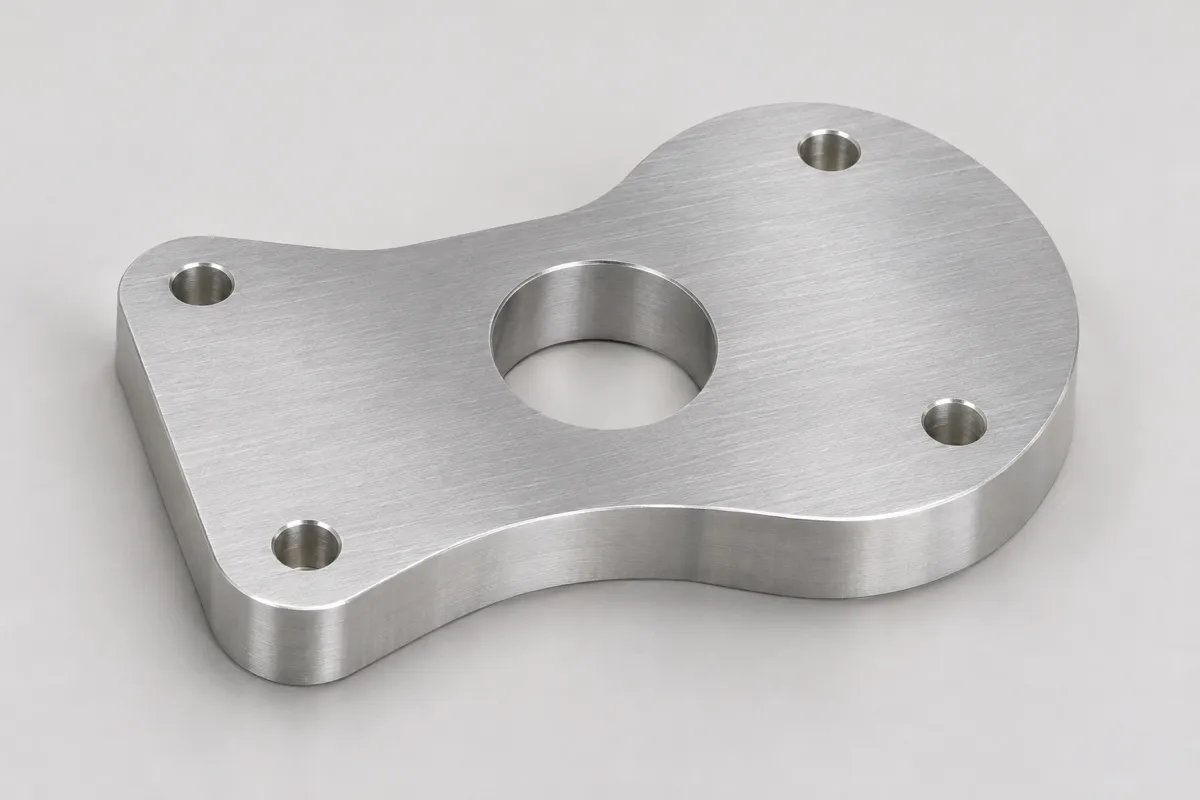
The PTC Creo GD&T glossary defines it as the symbolic means of indicating that a tolerance applies to surfaces all around the part; on the drawing it is a small circle at the bend of the leader from the feature control frame. In practice “all around the part” is read in the view: for a plate drawn in plan view, it covers the side walls that form the outline, not the top and bottom faces. Without the circle, a profile callout covers only the surface the leader points to, up to the next corner or break.
That is why the symbol saves so much drawing space and causes so many arguments. One small circle can turn a single-face profile into a requirement on a dozen surfaces, and each of them must then be inspected.
| Symbol | How it is drawn | What it controls | Common misreading |
|---|---|---|---|
| All around | One circle at the leader bend | All surfaces around the outline in the view shown | Read as the whole part, including top and bottom faces |
| All over | Two concentric circles at the leader bend | All surfaces of the part | Confused with all around because the circles look alike in a scan |
| Between | Double-headed arrow between two letters, e.g. A↔B | Only the segment between the lettered points | Applied to the wrong side of the outline when the letters are not clearly placed |
| CF, continuous feature | Letters CF next to the dimension or frame | Interrupted surfaces treated as one feature | Ignored, so each segment is inspected on its own |
How is all over different from all around?
All over, drawn as two concentric circles, applies the profile tolerance to every surface of the part in three dimensions, while all around stays with the outline in the view shown.
All over is a symbol defined in ASME Y14.5 and is the natural callout for a casting or a sculpted part checked against its model: one profile frame, every face. It is also a much larger inspection job, because every face needs measuring, usually by scanning or dense probing against the CAD model.
Because the two symbols differ only by one ring, a faint print or a low-resolution scan can blur them. If the drawing is going overseas as a PDF, a note such as “ALL OVER” beside the frame costs nothing and removes the doubt.
What does the between symbol do?
The between symbol limits a tolerance to a stated segment of a surface, from one lettered point to another, so the rest of the outline is not controlled by that callout.
Per the PTC Creo GD&T glossary, the points are designated with letters on leaders, and the letters sit on each side of a double-headed arrow under the feature control frame. Use it when only part of an outline is functional, such as a seal land, a cam track or the contact face of a clamp, and give the rest of the outline a looser profile or leave it to the general tolerance.
Two habits avoid trouble: put the letters exactly at the ends of the controlled segment, and say on the drawing which way round the segment runs if the outline is closed, because a closed contour has two paths between any two points. A tolerance that lands on the wrong path is a common source of rejected parts that are actually fine.
What does CF, continuous feature, mean?
CF tells the reader that two or more interrupted surfaces, such as a bore broken by a groove or a face split by a slot, are to be treated as one single feature for the tolerance or size requirement.
Without CF, a bore interrupted by an O-ring groove is two separate bores, each with its own size and form, and they may be offset from each other while each is individually in tolerance. With CF, the two segments must fit one common size and form, which is usually what the designer meant. Per the ASME vs ISO comparison chart, the continuous feature symbol exists in ASME but not in ISO GPS, so a drawing made to ISO rules needs a different method to say the same thing.
Inspection changes with it: a single plug gauge or a single fitted cylinder across both segments, instead of two separate checks.
How should profile extent be written so a supplier reads it correctly?
Name the standard and edition on the drawing, use one extent symbol per callout, and add a short word note where a print may be unclear.
Write “DIMENSIONING AND TOLERANCING PER ASME Y14.5-2018” in the title block or notes. The editions differ in detail, and a supplier who reads the drawing to the wrong edition can misapply a symbol in good faith. If the drawing mixes ASME and ISO habits, settle on one; the all around circle exists in both systems, but the rules around it are not identical.
For profile tolerances on castings, where all over and between are most common, our profile tolerance for castings guide covers datum choice and zone size, and the profile of a line vs surface guide covers which profile type to use.
| Design intent | Use | Why |
|---|---|---|
| Control the outside contour of a plate or extrusion-like part in one view | All around | One callout covers the full outline |
| Control every surface of a cast or molded part to a model | All over | One callout, all faces, model-based check |
| Control only a sealing land or a cam segment | Between | Tolerance stays off the non-functional rest of the outline |
| Treat a bore split by a groove, or a face split by a slot, as one | CF | One feature, one size or form requirement across the gap |
| Different tolerances on different segments | Separate callouts with between | Each segment gets its own frame |
How are these callouts inspected, and how does Saola handle them?
An all over or long all around profile usually needs scanning or dense probing against the model, so the inspection method is agreed at drawing review before the order.
The lead plant’s inspection equipment includes a 2D optical vision measuring instrument and a height gauge, and there is no CMM. A 2D outline in one view, the typical all around case on a flat part, suits the vision instrument; a three-dimensional all over profile does not, and the review says so and proposes a practical alternative, such as checking defined sections or functional gauges. New parts get a first-article inspection report and every lot a dimensional inspection record.
For castings that are machined on our CNC milling line, the machined faces and bores are usually the controlled features; mark which callouts apply to as-cast surfaces and which to machined ones, so the inspection plan matches.
Frequently asked
Does the all around symbol apply to holes inside the outline?
No. It applies to the surfaces forming the outline the leader points to in that view. Internal holes and pockets need their own callouts.
Does all around include the fillets and chamfers on the outline?
Yes. Every surface that forms the outline in that view is included, so corner radii and edge breaks on the contour fall under the profile tolerance too. Exclude them with a between callout or a note if that is not the intent.
What is the difference between CF and the old “2 SURFACES” note?
A note such as 2 SURFACES or 2X can mean two separate features with the same requirement. CF says the surfaces act as one feature, which is a tighter, different requirement.
Is the all around symbol used in ISO drawings too?
Yes, ISO 1101 also uses a circle for all around, but the surrounding rules differ from ASME. Read an ISO drawing by the ISO rules it names.
Why did the inspector reject the top face when the profile was all around?
Usually because the symbol was read as all over. Point to the view the callout sits in, and if needed add a note limiting the extent.
Sources
- ASME Y14.5-2018, Dimensioning and Tolerancing, ASME, 2018
- Creo Elements/Direct Modeling GD&T Advisor glossary (all around, between), PTC, accessed November 2026
- Major Differences between ASME Y14.5 and ISO GPS (chart hosted on the ZEISS Quality Forum), GD&T Basics, referencing ASME Y14.5-2018, accessed November 2026